
Before studying bilge piping we need to know about what’s bilge,
Page Contents
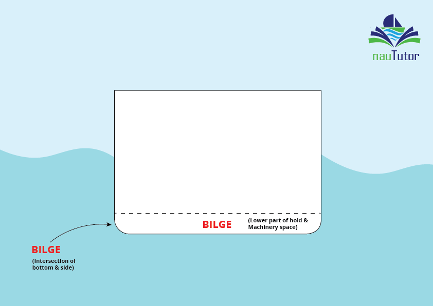
Bilge
- Means The intersection of bottom and side. or The lower parts of holds and machinery spaces where bilge water may accumulate.
- The purpose of the bilges are to collect oil and water mixture in the machinery space and water in the form of ship and cargo sweat in the cargo holds. The bilges can then be either pumped to a holding tank or overboard in accordance with MARPOL regulations.
Important points to remember;
Below are some concise points to keep in mind for your exam.
- Bilge pumping and piping arrangements in every cargo ship should, in general, be capable of discharging water from any compartment when the ship is on an even keel or listed not more than 5° either way.
- In the machinery spaces, additional arrangements must be made to ensure that any water can be discharged through two bilge suctions, one connected to the bilge main and one to an independent pump.
An emergency suction must also be provided with a connection to the main circulating water pump in the case of a steamship or to the main cooling water pump in the case of a motor ship. - Steel, copper, cast iron, or other approved materials may be used to construct bilge and ballast lines.
Lead and other heat-sensitive materials should not be used. - You can draw the diagram below for exams;
Bilge & ballast piping system drawing
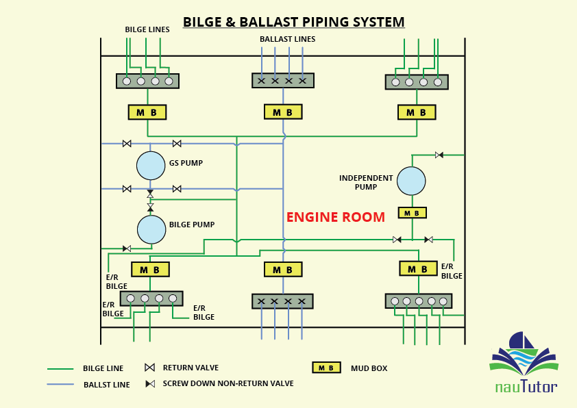
- There is a formula that takes into account the ship’s primary measurements and determines the size of the bilge lines, which must never be less than 50 mm bore.
- Provision for expansion is made in the form of expansion bends or glands.
- In order to protect the pumps, mud boxes are installed on the suction bilge lines from equipment compartments, and screw-down non-return valves must be installed on bilge lines.
- Strum boxes are fitted to the ends of suction bilge lines from spaces outside the machinery spaces. These strum boxes have perforations (holes) not more than 10 mm in diameter with a total area of at least twice that required for the bore of the suction pipe. It should be possible to clear the strums without breaking any joint in a suction pipe.
- Cargo ships must have at least two power-operated bilge pumps, one of which may be operated by the main engines.
- The bilge system is designed solely for overboard discharge, whereas the ballast system can discharge overboard, pump water into the tanks. and if needed, fill tanks through gravity.
- The forepeak tank is equipped with a screw-down valve that must be operated from above the bulkhead deck. This valve is located inside the tank.
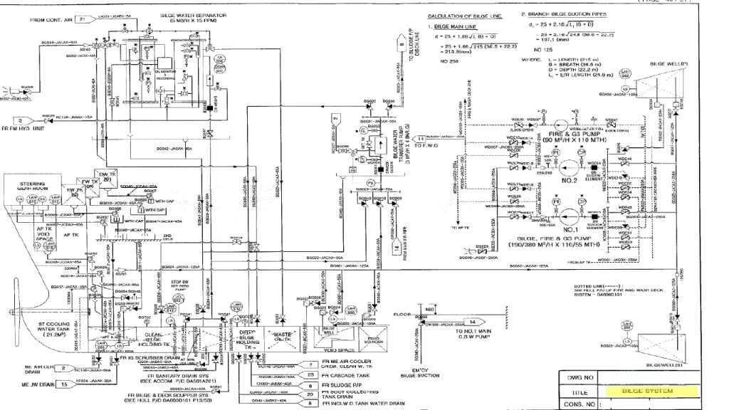
Bilge piping system drawing of a VLGC
below is the drawing of bilge system of a very large gas carrier,
You have got some solid exam points, but For more detailed information on this topic, please check out the link https://shipfever.com/bilge-and-ballast-system/
That’s all for today, I hope you have gained a clear understanding of the topic. If you have any questions or uncertainties about this topic, please don’t hesitate to leave a comment in the section below.
Thank you, 🤗
By Team Naututor
Amazing content and the very easiest way of explanation. It’s really helpful for Nautical Students.
Awesome 👍🏻
Thank you for your comment. Be a part of Naututor community.🥰